DIN 2353 vs Uni-Lok Twin Ferrule Tube Fittings
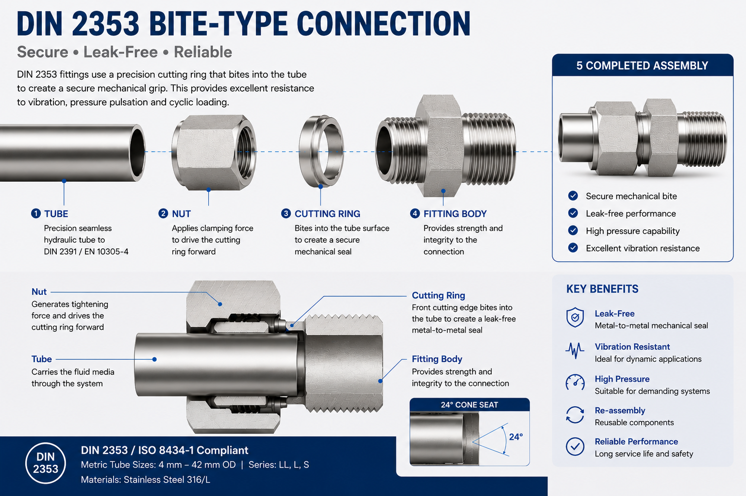
A DIN 2353 cutting-ring connection uses one cutting ring between the nut and body. Fluidline supplies Uni-Lok twin ferrule tube fittings, which use separate front and back ferrules. These are different connection systems: select the complete matched assembly for the application.
| Feature | DIN 2353 cutting-ring connection | Uni-Lok twin ferrule tube fittings |
|---|---|---|
| Components around the tube | One cutting ring and a union nut, used with a matching 24° body seat. | Separate front and back ferrules, a nut and the matching fitting body. |
| Operating principle | The nut drives the cutting ring onto the tube during the specified assembly procedure. | The two ferrules work together to form the tube seal and grip; their precise action depends on the design. |
| How to specify | Tube OD, LL/L/S series, material, ring system and all connection details. | Tube OD, material, Uni-Lok fitting series and all connection details. |
| Assembly instructions | Use the supplied cutting-ring system instructions and its inspection method. | Use the supplied Uni-Lok assembly instructions and inspection method. |
| Parts substitution | Do not replace its ring with a twin-ferrule set. | Do not replace its ferrules with a DIN cutting ring. |
One Ring Does Not Mean One Cutting Edge
“Single ferrule” describes the number of separate ring components. A ring may have more than one cutting edge. Count and identify the components using the supplied product drawing, rather than inferring the design from marketing terminology.
Neither ferrule count nor the term “compression fitting” establishes a universal pressure rating or suitability for a particular fluid. Confirm the exact fitting, tubing, material, temperature limits and assembly requirements.
Fluidline’s twin ferrule brand: Uni-Lok twin ferrule tube fittings. For the DIN 2353 connection standard, see the ISO 8434-1 scope. Use matched components and the instructions for the selected fitting system.
Cutting-ring part numbers and dimensions →
Matching tube nuts →
L and S series comparison →
Prepare the Work and Confirm the Components
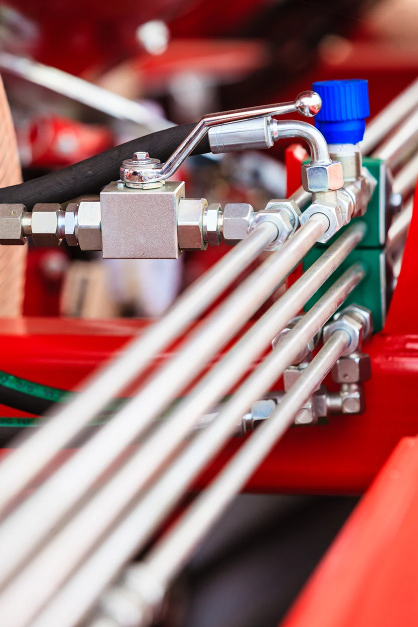
Before opening a hydraulic connection, isolate the equipment and release stored pressure using the equipment procedure. Consider accumulators, supported loads and trapped fluid. Never loosen or retighten a fitting while it is pressurised. Keep the work area clean and protect open ports and tube ends against contamination.
Check the fitting configuration, tube outside diameter, LL/L/S series, tube wall and material before assembly. Confirm that the body, nut, cutting ring and any seals form an approved combination. Inspect the threads and sealing surfaces for damage. Obtain the assembly instructions for the supplied system, including any requirements for tools, lubrication, preassembly and inspection.
Prepare and Support the Tube
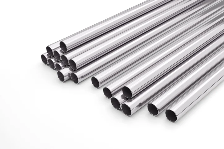
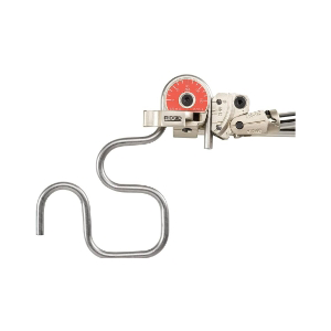
Cut the tube square using the equipment specified for the system. Remove internal and external burrs without creating an excessive bevel, then clean away chips and debris. Check that the tube end is round, straight and undamaged over the length needed for assembly. Confirm the minimum straight length near a bend before cutting the tube.
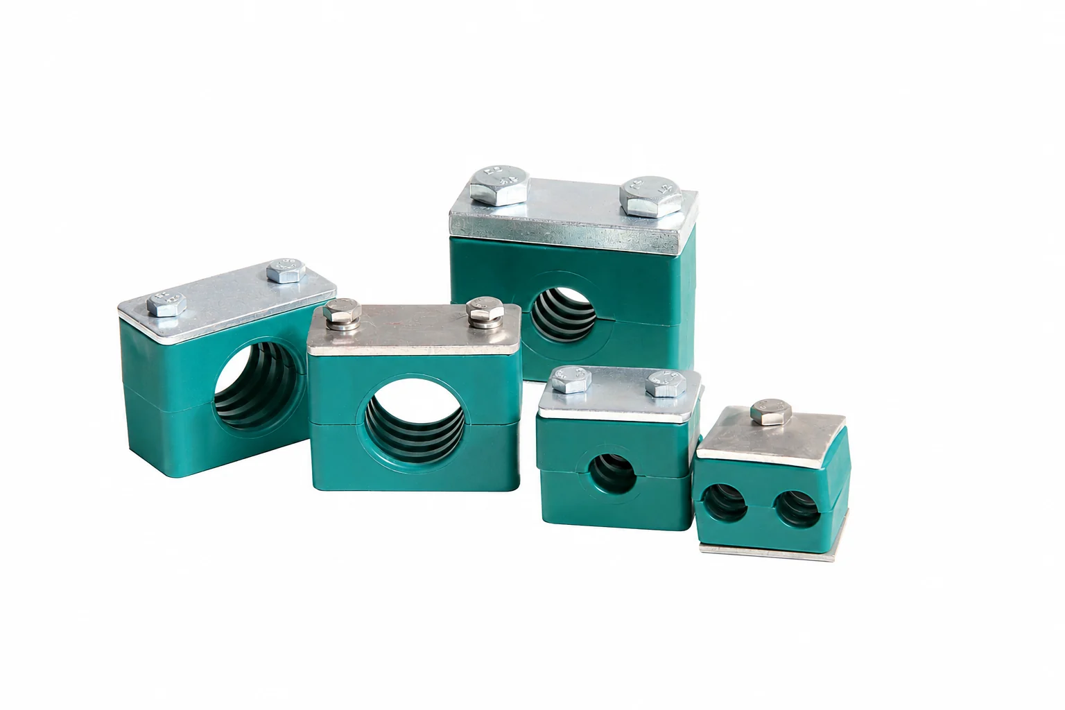
Use tubing that meets the specified dimensional, material and hardness requirements. Where support sleeves are required, select the approved size and type. Route the tube so the connection can be assembled without forcing misaligned parts together. Fit suitable tube supports to manage vibration and avoid leaving the fitting to carry unnecessary mechanical loads.
Follow the Supplied Assembly Method
Place the nut and cutting ring on the tube in the correct orientation. Keep the tube firmly against the specified stop during the cutting-ring operation. Use the prescribed preassembly tool or machine where required, particularly when the instructions specify this for stainless steel, larger sizes or a particular connection design.
Apply lubrication only as directed for the components and assembly method. Surface finishes and materials can change friction and tightening behaviour. Use the stated inspection method to confirm that the ring has formed correctly and retained the tube. A visible material collar may be part of a conventional cutting-ring inspection, while other sealing systems use different checks.
Complete the joint using the specified final assembly procedure and hold the body as instructed. There is no single tightening torque or number of turns that applies to every DIN 2353 fitting. Manual preassembly, machine preassembly and different ring designs can require different final assembly steps.
Inspect, Commission and Maintain the Connection
After assembly, check the installation for alignment, support, clearance and cleanliness. Commission and inspect for leakage using the equipment and site procedures. Keep hands away from suspected hydraulic leaks: a small pressurised jet can cause serious injury. If a connection needs correction, isolate and depressurise the system first.
During maintenance, protect dismantled parts and inspect the tube end, ring, nut, body and seals. Replace damaged or unsuitable components. Preserve matched assemblies where the supplied instructions require this, and use the specified reassembly procedure. Reuse depends on component condition and system instructions; repeated disassembly does not justify an unlimited service-life assumption.
- Confirm the tube, series and complete component combination before assembly.
- Use the specified tools and inspection criteria; check tools for wear.
- Retain the supplied assembly instructions with maintenance records.