
Welding Connectors
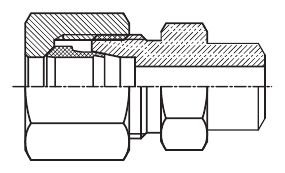
Join a cutting-ring tube connection to a weld-end body.
Configuration illustration; supplied variant may differ.
Query product →Specify F-Line weld connectors, nipples, reducers and weld bulkhead connections for hydraulic tube assemblies that require a welded transition. Match the weld end to tube material and wall thickness.
ISO 8434-1 is the equivalent international standard for DIN 2353 24° cone tube connections.
Join a cutting-ring tube connection to a weld-end body.
Configuration illustration; supplied variant may differ.
Query product →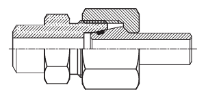
Specify the welding connector and its matched nipple assembly.
Configuration illustration; supplied variant may differ.
Query product →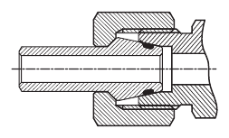
Select a welding nipple for the required tube dimensions.
Configuration illustration; supplied variant may differ.
Query product →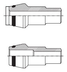
Reduce the tube connection at the welding nipple.
Configuration illustration; supplied variant may differ.
Query product →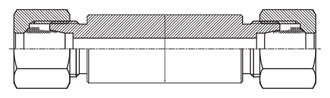
Pass a tube assembly through a weld-in bulkhead connection.
Configuration illustration; supplied variant may differ.
Query product →Use the Fluidline part number in your enquiry. SS identifies stainless steel in this list; confirm the exact supplied grade and configuration.
Search all 105 Fluidline part numbers → · Browse dimensional tables ↓
For this range, request a Fluidline part number using the configuration and dimensions below.
Choose a configuration to open its drawing and sizes. Linear dimensions are in mm. Upper-case L and lower-case l are different drawing dimensions. A dash means the catalogue does not provide a value.
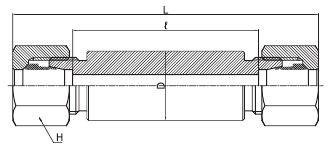
Dimensions in millimetres. Thread designations are shown separately. Match the letters to the drawing.
Catalogue drawing and table — page 30| Fluidline part number | Series | Tube OD (mm) | H | D | L | l |
|---|---|---|---|---|---|---|
| On enquiry | L | 6 | 18 | 14 | 85 | 56 |
| On enquiry | L | 8 | 20 | 17 | 85 | 56 |
| On enquiry | L | 10 | 22 | 19 | 87 | 58 |
| On enquiry | L | 12 | 25 | 22 | 87 | 58 |
| On enquiry | L | 15 | 28 | 27 | 100 | 70 |
| On enquiry | L | 18 | 32 | 32 | 101 | 69 |
| On enquiry | L | 22 | 36 | 36 | 105 | 73 |
| On enquiry | L | 28 | 40 | 41 | 106 | 73 |
| On enquiry | L | 35 | 50 | 50 | 114 | 71 |
| On enquiry | L | 42 | 60 | 60 | 115 | 70 |
| On enquiry | S | 6 | 20 | 17 | 89 | 60 |
| On enquiry | S | 8 | 22 | 19 | 89 | 60 |
| On enquiry | S | 10 | 25 | 22 | 91 | 59 |
| On enquiry | S | 12 | 28 | 24 | 91 | 59 |
| On enquiry | S | 14 | 30 | 27 | 107 | 72 |
| On enquiry | S | 16 | 35 | 30 | 107 | 71 |
| On enquiry | S | 20 | 38 | 36 | 114 | 71 |
| On enquiry | S | 25 | 45 | 46 | 120 | 72 |
| On enquiry | S | 30 | 50 | 50 | 126 | 73 |
| On enquiry | S | 38 | 60 | 60 | 133 | 72 |
Reference dimensions support selection. Confirm the supplied item drawing, material, seals and permissible operating conditions with your quotation.
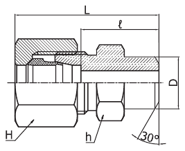
Dimensions in millimetres. Thread designations are shown separately. Match the letters to the drawing.
Catalogue drawing and table — page 59| Fluidline part number | Series | Tube OD (mm) | D | H | h | L | l |
|---|---|---|---|---|---|---|---|
| On enquiry | L | 6 | 10 | 14 | 12 | 29 | 14 |
| On enquiry | L | 8 | 12 | 17 | 14 | 31 | 16 |
| On enquiry | L | 10 | 14 | 19 | 17 | 33 | 18 |
| On enquiry | L | 12 | 16 | 22 | 19 | 33 | 18 |
| On enquiry | L | 15 | 19 | 27 | 22 | 37 | 22 |
| On enquiry | L | 18 | 22 | 32 | 27 | 40 | 22.5 |
| On enquiry | L | 22 | 27 | 36 | 32 | 45 | 28.5 |
| On enquiry | L | 28 | 32 | 41 | 41 | 47 | 30.5 |
| On enquiry | L | 35 | 40 | 50 | 46 | 54 | 32.5 |
| On enquiry | L | 42 | 46 | 60 | 55 | 58 | 35 |
| On enquiry | S | 6 | 11 | 17 | 14 | 34 | 19 |
| On enquiry | S | 8 | 13 | 19 | 17 | 36 | 21 |
| On enquiry | S | 10 | 15 | 22 | 19 | 39 | 22.5 |
| On enquiry | S | 12 | 17 | 24 | 22 | 41 | 24.5 |
| On enquiry | S | 14 | 19 | 27 | 24 | 45 | 27 |
| On enquiry | S | 16 | 21 | 30 | 27 | 45 | 26.5 |
| On enquiry | S | 20 | 26 | 36 | 32 | 51 | 29.5 |
| On enquiry | S | 25 | 31 | 46 | 41 | 56 | 32 |
| On enquiry | S | 30 | 36 | 50 | 46 | 62 | 35.5 |
| On enquiry | S | 38 | 44 | 60 | 55 | 69 | 38 |
Reference dimensions support selection. Confirm the supplied item drawing, material, seals and permissible operating conditions with your quotation.
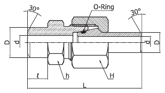
Dimensions in millimetres. Thread designations are shown separately. Match the letters to the drawing.
Catalogue drawing and table — page 68| Fluidline part number | Series | Tube OD (mm) | d | H | h | L | l |
|---|---|---|---|---|---|---|---|
| On enquiry | - | 10 | 8 | 22 | 19 | 58 | 10 |
| On enquiry | - | 12 | 9 | 24 | 22 | 63 | 15 |
| On enquiry | - | 16 | 13 | 30 | 27 | 73.5 | 16.5 |
| On enquiry | - | 20 | 16 | 36 | 32 | 83.5 | 19 |
| On enquiry | - | 25 | 19 | 46 | 41 | 92.5 | 19.5 |
| On enquiry | - | 30 | 24 | 50 | 46 | 101.5 | 23 |
| On enquiry | - | 38 | 30 | 60 | 55 | 108 | 22 |
Reference dimensions support selection. Confirm the supplied item drawing, material, seals and permissible operating conditions with your quotation.
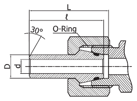
Dimensions in millimetres. Thread designations are shown separately. Match the letters to the drawing.
Catalogue drawing and table — page 69| Fluidline part number | Series | Tube OD (mm) | d | L | l |
|---|---|---|---|---|---|
| On enquiry | - | 10 | 8 | 33.5 | 32.5 |
| On enquiry | - | 12 | 9 | 33.5 | 32.5 |
| On enquiry | - | 16 | 13 | 40.5 | 39 |
| On enquiry | - | 20 | 16 | 47 | 45 |
| On enquiry | - | 25 | 19 | 53 | 49.5 |
| On enquiry | - | 30 | 24 | 57 | 52 |
| On enquiry | - | 38 | 30 | 64 | 56.5 |
Reference dimensions support selection. Confirm the supplied item drawing, material, seals and permissible operating conditions with your quotation.
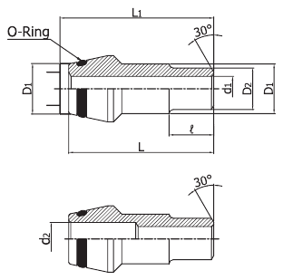
Dimensions in millimetres. Thread designations are shown separately. Match the letters to the drawing.
Catalogue drawing and table — page 70| Fluidline part number | Series | D1 | D2 | d1 | d2 | L1 | L | l |
|---|---|---|---|---|---|---|---|---|
| On enquiry | - | 10 | 6 | 3 | 5 | 34 | 33 | 12 |
| On enquiry | - | 10 | 8 | 4 | - | 34 | 33 | 12 |
| On enquiry | - | 12 | 8 | 4 | 6 | 34 | 33 | 14 |
| On enquiry | - | 12 | 10 | 7 | - | 34 | 33 | 14 |
| On enquiry | - | 16 | 12 | 7 | - | 41 | 39 | 15 |
| On enquiry | - | 20 | 12 | 7 | - | 47 | 45 | 17 |
| On enquiry | - | 20 | 16 | 10 | - | 47 | 45 | 17 |
| On enquiry | - | 25 | 16 | 10 | - | 53 | 50 | 20 |
| On enquiry | - | 25 | 20 | 12 | - | 53 | 50 | 20 |
| On enquiry | - | 30 | 16 | 12 | - | 57 | 52 | 22 |
| On enquiry | - | 30 | 20 | 15 | - | 57 | 52 | 22 |
| On enquiry | - | 30 | 25 | 19 | - | 57 | 52 | 22 |
| On enquiry | - | 38 | 16 | 12 | - | 64 | 57 | 26 |
| On enquiry | - | 38 | 20 | 15 | - | 64 | 57 | 26 |
| On enquiry | - | 38 | 25 | 19 | - | 64 | 57 | 26 |
| On enquiry | - | 38 | 30 | 22 | - | 64 | 57 | 26 |
Reference dimensions support selection. Confirm the supplied item drawing, material, seals and permissible operating conditions with your quotation.
DIN 2353 welding fittings are used in hydraulic tube assemblies where the design requires a permanent welded transition at the weld end. Depending on the configuration, another connection in the assembly may remain detachable.
Select the fitting to match the tube outside diameter, wall thickness, material grade and specified weld preparation. Provide the assembly drawing and project requirements for the welding procedure, inspection, pressure testing and documentation.
For stainless steel assemblies, specify suitable post-weld cleaning to address heat tint and contamination, together with the required internal cleanliness before commissioning.
Specify the tube outside diameter, LL/L/S series, material and every connection. The overall catalogue covers 4–42 mm tube, but an individual configuration may have a narrower range. Carbon steel, 316L and 316Ti can be included in an enquiry, subject to confirmation of the supplied item.
State whether you require complete fittings or bodies only. Include working pressure, peak pressure, temperature, medium and any certificate requirements so the complete assembly can be checked.
Select materials, seals and pressure capability →Identify a DIN 2353 connection by tube outside diameter, fitting series, thread and sealing form. A matching thread alone does not establish a correct connection.
Select the fitting, tube and seals as one assembly. Pressure capability depends on the exact configuration, material, tube dimensions, temperature and installation method.
Successful cutting-ring connections depend on suitable tubing, matched components, careful preparation and the correct assembly procedure for the supplied fitting system.
Identify the configuration, tube diameter and series, all connection threads and seals, material, quantity and operating conditions. Send a marked sketch when port positions or different end sizes matter.
Use them to identify and enquire about the configuration. Obtain the order-specific drawing and confirmed pressure rating before fabrication or installation.
Send the connection details and operating conditions. Fluidline can confirm the supplied configuration, availability and supporting documentation with your quotation.
+27 11 312 9339
ram@fluidline.co.za · brett@fluidline.co.za
Send your enquiry directly. We save your requirements and email Brett and Ram so they can respond. Privacy information.
Bring the whole assembly into your enquiry, from the connection and tube specification to the clamps that support the run.
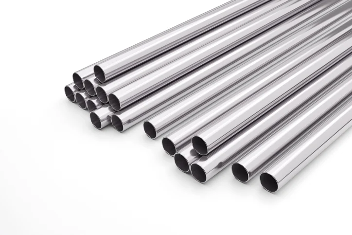
Specify tube outside diameter, wall thickness and material with your fittings. View tube OD and wall thickness sizes.
Explore tubing at Fluidline →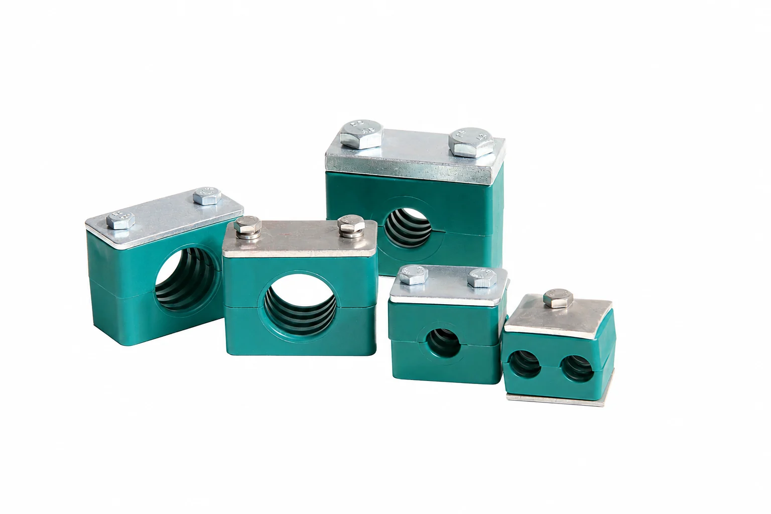
Include the tube diameter, mounting arrangement and support requirements.
Explore tube clamps at Fluidline →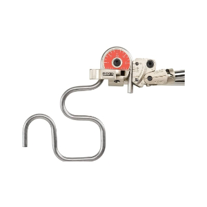
Prepare the tube run with bending, cutting and deburring tools suited to its diameter, wall thickness and material.
Explore tube tools at Fluidline →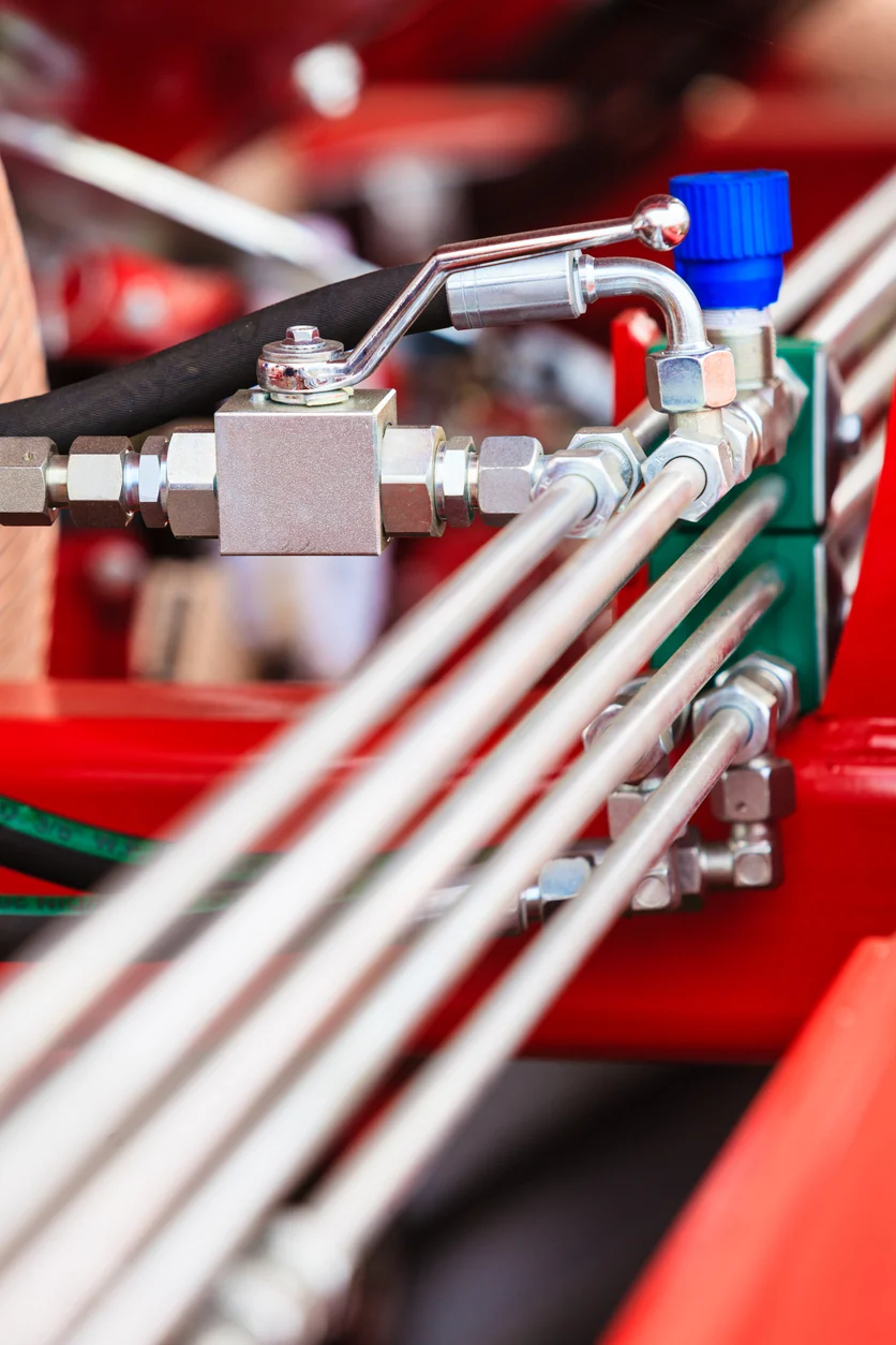
Review tube preparation, component matching and inspection before assembly.
Read the installation overview →