Start with the tube outside diameter
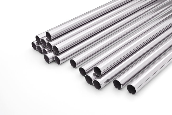
DIN 2353 fittings connect metric hydraulic tube using a cutting ring, union nut and a fitting body with a 24° seating interface. Measure the tube outside diameter in millimetres with a suitable measuring tool. Do not substitute the tube bore, hose nominal size or spanner size. Record the tube wall thickness as well: it affects tube suitability and the pressure capability of the assembly.
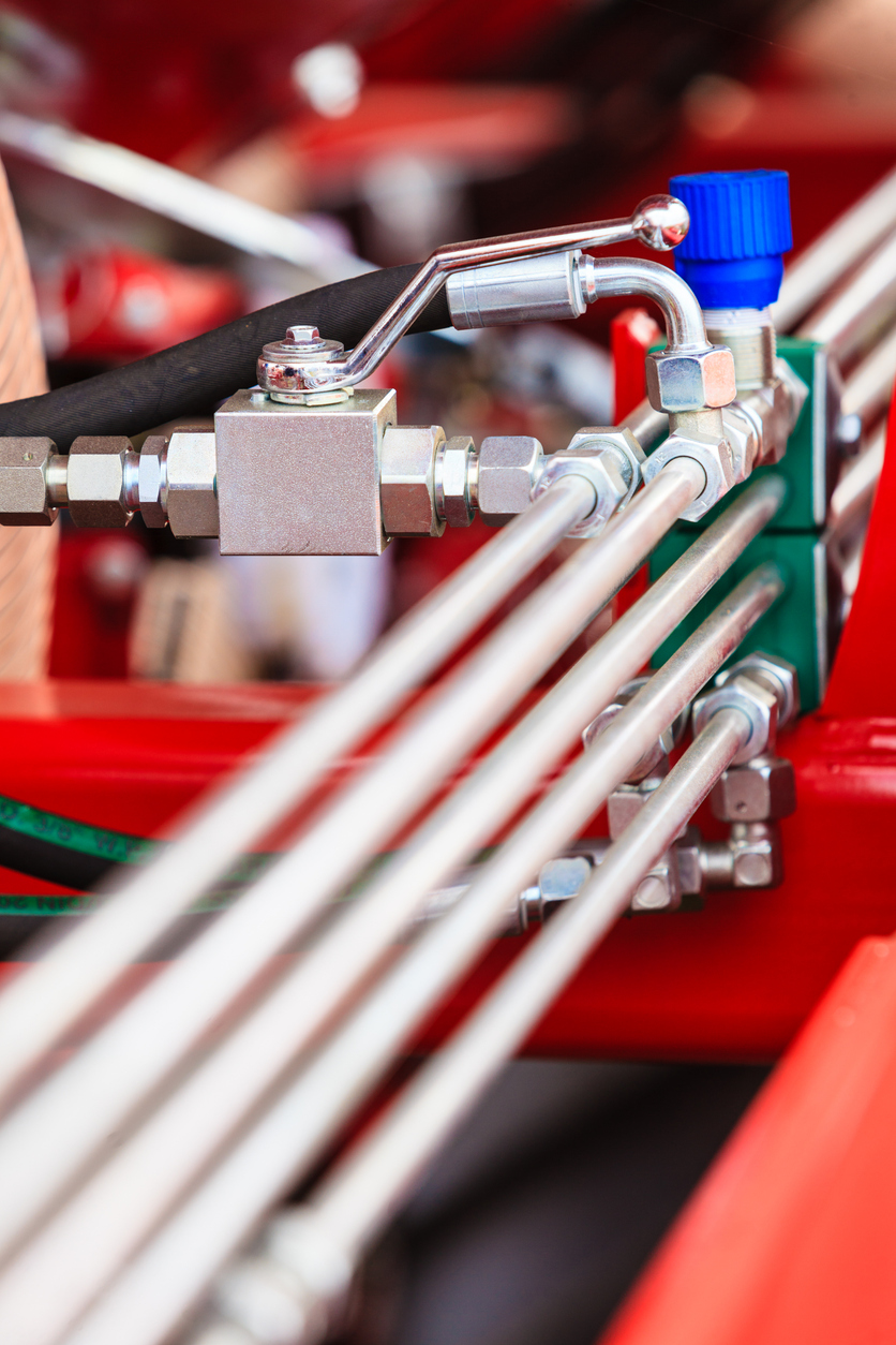
For an existing installation, read any visible series or size markings and photograph the fitting before disassembly. A photograph helps identify the configuration, but measurements and connection details are still needed. If the fitting is installed, isolate the equipment and release stored pressure before removing components for inspection.
Select the correct LL, L or S series
LL denotes the very light series, L the light series and S the heavy series. The catalogue selection scope covers LL tube sizes from 4 to 12 mm, L from 6 to 42 mm and S from 6 to 38 mm. Individual configurations and supplied ranges can be narrower, so confirm availability for the exact combination requested.
Series letters identify a dimensional family; they are not a complete pressure specification. The same tube diameter can appear in more than one series with a different union thread, nut and body. For example, a 6 mm L-series tube connection uses M12×1.5, while a 6 mm S-series connection uses M14×1.5. Specify the diameter and the series together, such as 6L or 6S.
Find the tube-end union thread
Identification aid only. Match the series, tube size and seating arrangement as well as the thread.
| Series | Tube OD mm | Union thread |
|---|---|---|
| LL | 4 | M8 × 1 |
| LL | 6 | M10 × 1 |
| LL | 8 | M12 × 1 |
| LL | 10 | M14 × 1 |
| LL | 12 | M16 × 1 |
| L | 6 | M12 × 1.5 |
| L | 8 | M14 × 1.5 |
| L | 10 | M16 × 1.5 |
| L | 12 | M18 × 1.5 |
| L | 15 | M22 × 1.5 |
| L | 18 | M26 × 1.5 |
| L | 22 | M30 × 2 |
| L | 28 | M36 × 2 |
| L | 35 | M45 × 2 |
| L | 42 | M52 × 2 |
| S | 6 | M14 × 1.5 |
| S | 8 | M16 × 1.5 |
| S | 10 | M18 × 1.5 |
| S | 12 | M20 × 1.5 |
| S | 14 | M22 × 1.5 |
| S | 16 | M24 × 1.5 |
| S | 20 | M30 × 2 |
| S | 25 | M36 × 2 |
| S | 30 | M42 × 2 |
| S | 38 | M52 × 2 |
These are tube-end threads, not equipment port sizes. Confirm the exact supplied range; not every family covers every size.
Separate the tube union thread from the equipment port
A male connector has two connection descriptions. One end accepts the tube and its nut; the other screws into an equipment port. The metric thread in the tube-end chart belongs to the union connection. It does not tell you the size or sealing arrangement of the equipment port.
Record whether the port thread is metric, BSP parallel, BSP tapered or NPT, then confirm its size, pitch and sealing form. Parallel port connections may seal with a specified ring, washer or sealing face. Tapered threads use a different sealing arrangement. Thread sealant is not a substitute for a missing tube cutting ring, damaged cone or incorrect port seal.
Check the whole connection before ordering
Several different tube connections share a thread. For example, 8L and 6S both use M14×1.5, although their tube diameters and series differ. Check the seat, tube diameter and series rather than relying on whether a nut starts on a thread. Keep matched components together and obtain compatibility confirmation before combining parts from different fitting systems.
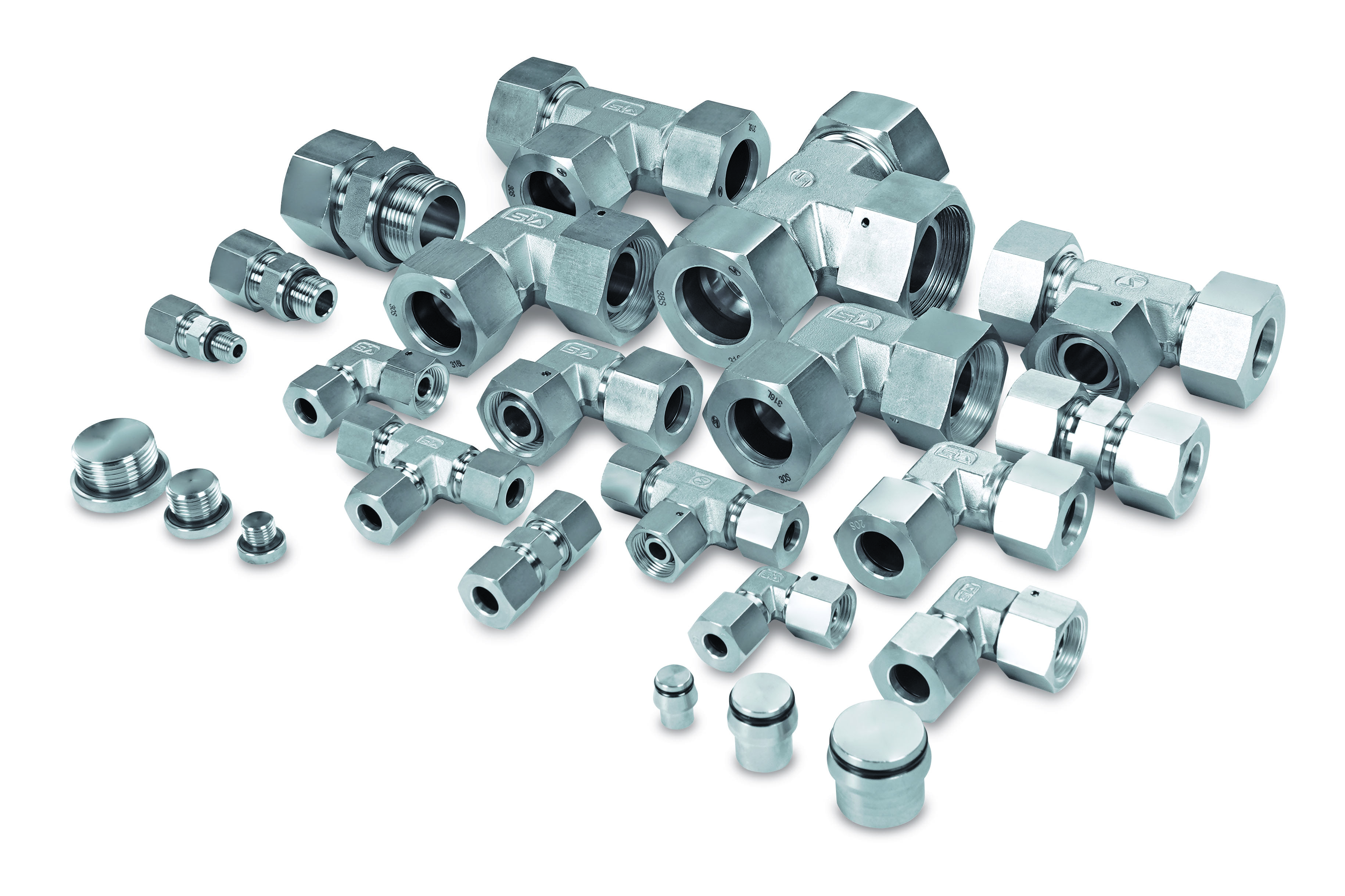
For tees and crosses, identify each port separately on a sketch. State which ports form the run and which are branches. For bulkhead fittings, include the panel requirement; for elbows, include orientation and clearance. Specify whether you need a complete fitting with nut and cutting ring or a body only.
- Send tube outside diameter, wall thickness and LL/L/S series.
- Describe every port thread and seal, with photographs or a drawing.
- Include fitting shape, material preference, quantity and operating conditions.